IDCS - The Insertion Device Control System of BESSY II
Preface
This document describes the major components and interfaces of IDCS, the Insertion Device Control System at the BESSY II synchrotron facility. IDCS is a system of hard- and software-components that controls the movement of undulators installed at the facility. The undulators are also named Insertion Devices.
A Brief introduction to Insertion Devices
Undulators are magnetic structures that are used to create radiation when the electron beam passes between them. These structures consist of 2 parts above and below the electron beam that can be moved against each other. This vertical movement changes the characteristic of the radiation that is created.
For some undulators, the structures above and below the electron beam are doubled and each can be moved to the left and to the right side, this is called a shift drive.
The following paragraph describes a standard design of a BESSY undulator, note that some undulators are more complicated and have more ways to be moved and more motor axles to control.
The magnetic structures usually consist of (this is a simplified description) four large bars. Two of them are in one line above and two are below the electron beam. Each end of each bar can be moved up or down. The movement of two ends that are in one vertical line is mechanically coupled. Overall there are four motors that can be driven to move the bars (plans exist for Insertion Devices with four additional motors instead of the mechanical coupling).
The major task of the Insertion Device Control System is to control the movement of these magnetic structures. Two different kinds of movement have to be supported in the end, the first kind is fully supported, the second kind is currently (as of 2023-04-19) beeing tested:
Moving to fixed positions: The magnetic structures are moved to a certain position. The kind of the movement (it’s velocity) is not critical.
Controlled movement or continuous mode: The structures have to be moved from one position to another with a certain velocity. During this movement, the velocity has to be changed according settings from the monochromator control system.
At all times, the position of the magnetic structures has to be monitored. Two systems need this information, the machine control system and the monochromator control system. The position is given in form of the size of the vertical gap between each pair of magnetic structures (“magnetic gap”). During movement, this information has to be provided about 10 times a second.
Each time the magnetic structures are moved, several security checks have to be made in order to avoid damage to the Insertion Device:
Before movement a “sanity check”is performed on the movement parameters. It is checked whether they are within the allowed range.
The End-position switches are monitored
The declination of the bars is checked (only a very small declination is allowed)
It is checked whether the motors start and stop their movement according to the commands from the Insertion Device Control System
Overview over major components of IDCS
Hardware-Components
IDCS consists of 2 major hardware components, the ID-IOC and the motor control device. The motor control device is either the MOCON or the UniDrive system.
Attention
The “mocon” device is deprecated, all new undulators use the “unidrive” device.
Note that the magnetic structures, the motors, the position measurement system and the power electronic equipment of the motors are not part of IDCS, but are part of the Insertion Device (ID) itself.
The ID-IOC
This is a VME-BUS based computer or a Linux-PC that is part of the Machine Control System. The Machine Control System has many more IOC’s that are either VME-BUS based computers or Linux-PCs, but the ID-IOC is used solely to control a single Insertion Device. Each IOC has an Ethernet-interface which connects it to the rest of the control system. It also has 4 interfaces for the CAN bus, which is a real-time bus used at BESSY II. The CAN-BUS connects the IOC to:
A central IOC that is used to collect Gap-Values (Collector-IOC)
A MC-IOC that is used to steer a monochromator and provides the steering-commands for the ID-IOC
The motor control devices, either a single MOCON or several UniDrive devices that control all motors of an Insertion device.
Only when the MOCON device is used, and the ID-IOC is a VME host, the ID-IOC has also a direct connection to the position measurement system that is used in parallel with the position measurement of the MOCON.
With the UniDrive motor control, all position measurement takes place on the motor control device and the IOC reads positions via the CAN Bus from the UniDrive devices.
The MOCON
This is the old motor-control device that is used to control the motors. It is programmable in a kind of BASIC-dialect and has a CAN-BUS interface. The position measurement system is directly connected to the MOCON’s built-in motor steering unit.
The UniDrive
This is the new motor-control device that is used for motor control. It is programmable in a kind of Pascal-dialect and has a CAN-BUS interface. The position measurement system is directly connected to the UniDrive. Each UniDrive device controls a single motor. All are connected to the same CAN-Bus line.
Software-Components
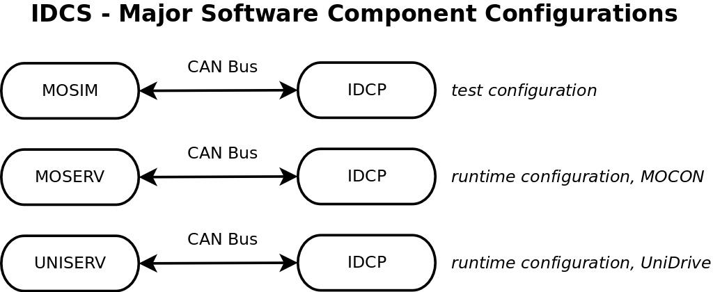
IDCS consists of two major software components, IDCP and MOSERV or UniServ. In order to simplify the development of these, another component is added, MOSIM. These software modules can be used in different configurations.
IDCP
IDCP is the Insertion Device Control Program. This is the program that runs on the IOC. The program receives commands via the CAN-BUS from the MC-IOC. It informs the Machine Control System of the movement, calculates gap-values from given energy values (the MC-IOC provides only the energy of the wanted radiation) and transmits the needed movement-parameters to the motor control device. During movement, it receives the current gap-values from the motor control device, checks and compares them with it’s own gap-values and sends them to the Collector-IOC and the MC-IOC. IDCP uses EPICS, which is a software-packet that runs on all IOC’s and forms (together with System-Operator workstations) the control system of the storage ring. EPICS is too complex to be described it here in detail. Put into a few words, it is a distributed real-time data-base. Each process-variable is part of that data-base. All data-base variables are stored in structures called Records. Records can interact with each other on one IOC and across the (TCP/IP-) network with other IOC’s. They can also be read, displayed and modified from the Operator-Workstations. A program that uses EPICS is not simply written in a programming language but it is essentially a set of record-specifications and connections between them. Parts of such a program can be ordinary C-Code (with the EPICS-Sequencer) but this is avoided when possible in order to keep a clean and straight-forward approach.
MOSERV
MOSERV is the Motor-Control Server Program. It runs on the MOCON device. Since the MOCON device can only be programmed in a simple (BASIC-like) programming language which is based on a slow interpreter, no complex tasks are performed by MOSERV. MOSERV essentially receives parameters from the CAN-BUS and starts the motor-movement when an appropriate command is received via the CAN-Bus. It also sends the current gap-positions during this movement as fast as possible via the CAN-Bus to the ID-IOC.
MOSIM (a Test-Program)
This is a portable C-program that is used to simulate the MOCON device. It runs on a dedicated test-IOC and prints out all motor-movements that would have been performed by the MOCON device. This program is useful for the development of IDCP since the MOCON device is physically connected to an Insertion-Device and cannot be moved.
UNISERV
UNISERV is the Motor-Control Server Program that runs on the UniDrive device. The UniDrive can be programmed in a Pascal-like programming language.
UNISERV receives parameters from the CAN-BUS and starts the motor-movement when an appropriate command is received via the CAN-Bus. It also sends the current gap-positions during this movement as fast as possible via the CAN-Bus to the ID-IOC.
UNISERV can also change the movement velocity while the axles are moving. This can be done directly, via a CAN Bus command or by a movement table that can be downloaded to the device via the CAN Bus.
External Interfaces
The MC-IOC Interface
The ID-IOC has a CAN-Bus connection to the MC-IOC. The LowCAL protocol is used on this connection. LowCAL is a CAN-protocol and is part of MultiCAN. MultiCAN is a set of software-components that adds CAN-Bus support to EPICS. MultiCAN consists of GPS (Generic Protocol Support), LowCAL (subset of the CAL-Protocol), SCI (Simple CAN Interface) and VCAN (VME-CAN2 Driver). These components are also explained in Section “Existing Software-Components used by IDCS” below.
The Machine Control System Interface
The ID-IOC has two connections to parts of the Machine Control System. First there is the connection via EPICS to the System Operator Workstations. Since EPICS provides all necessary functions for that connection, no additional work has to be done on side of the ID-IOC. The 2nd connection is the CAN-Bus connection to the Collector-IOC. This IOC gathers all gap-values from all ID-IOC’s in the storage ring. This connection uses the LowCAL protocol in order to read the state and current positions of each ID-IOC. The Collector-IOC can also issue a “home” command to move an insertion device to it’s home position before injection in the storage ring.
The Motor-Interface
This interface is only mentioned here only for completeness. It is already realized within the MOCON or UniDrive device and provides all commands that are necessary for controlling the motors of the Insertion Device.
The Measurement System Interfaces
The measurement system provides analog signals that are used to measure the magnetic gaps at a very high precision. These signals are fed into the MOCON or UniDrive device.
In case of the MOCON, the IOC also has a second independent interface to the position measurement system, in case of the UniDrive the IOC gets positions from the UniDrive via the CAN Bus.
Internal Interfaces
The IDCS consists of 2 hardware components, each equipped with a single software component. The hardware-components, the ID-IOC and the MOCON or UniDrive are connected via the CAN-Bus. The software-components, IDCP and MOSERV or IDCP and UNISERV communicate via the CAN-Bus. In case of MOSERV, the protocol is LowCAL.
LowCAL introduces Multiplex-Variables which are a way to transport up to 127 different variables just with 2 CAN-objects. This is important, since the MOCON device only supports up to 3 CAN-objects. LowCAL is be used to implement a number of parameter-variables in MOSERV which can be read or written by the IDCP. There is also a command-variable in MOSERV which is used to start or stop the motor-movement. Several variables within IDCP are used by MOSERV to write back status-messages and gap-values.
In case of the UniDrive device, the CAN Bus protocol is CANOpen. CANOpen includes LowCAL (named “PDO” in this standard) but it also provides a slower way to possibly map hundreds of variables, called “SDO”.
Existing Software-Components used by IDCS
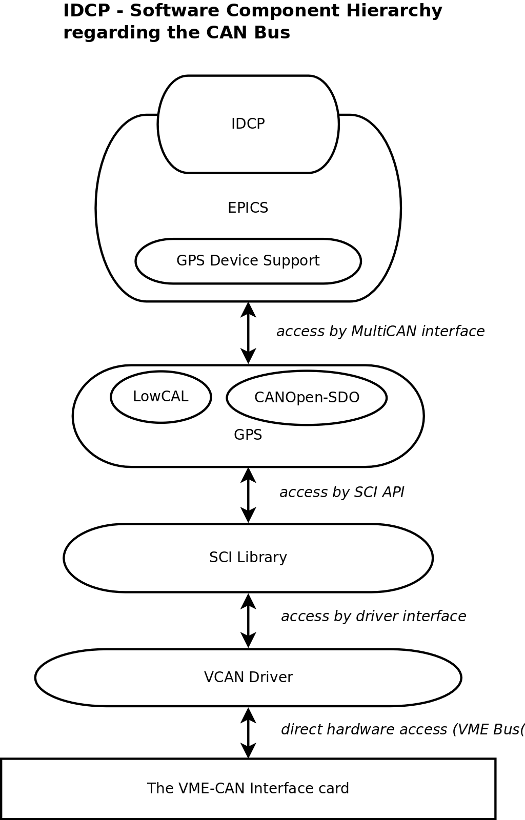
IDCS is based on a number of existing software-components that are partly bought by the Helmholtz-Zentrum Berlin and partly developments in house. These components are listed in the following paragraphs. The following picture shows the hierarchy of libraries on the ID-IOC:
Programming Languages
The following programming languages are used:
The MOCON is programmed in the MOCON-programming language. This language is similar to basic, but doesn’t need line-numbers.
The UniDrive device is programmed in the SM Application Module language. This language is similar to Pascal but without user data types or data structures.
The ID-IOC is programmed in C, parts are written in the EPICS state notation language.
Operating Systems
The following operating systems are used:
The MOCON has no real operating system but can execute just one program at a time. It has (aside from the connection to the motors of the Insertion Device) a serial and a CAN-Bus interface.
The UniDrive device also has no real operating system, but a hand full of tasks can be used. The main positioning task runs every 2 milliseconds. It has (aside from the connection to the motors of the Insertion Device) a serial (“CT-Net”) and a CAN-Bus interface.
The ID-IOC runs with the RTEMS operating system. This is an open source multitasking real-time operating system. It has a largely POSIX-compliant API.
For test purposes the program MOSIM uses the operating system vxWorks by WindRiver.
Drivers
Note that “driver”does not just mean a program that accesses hardware directly but a program the complies to certain standards of the operating system for device-drivers. The only driver used in that meaning is the VCAN-driver:
VCAN
VCAN is a portable driver for the VME-CAN2 and VME-CAN4 card, which is a CAN-Interface card for the VME-BUS. This driver was developed by Götz Pfeiffer at BESSY and is available for the RTEMS operating system. This driver is also used by all other IOC’s that are part of the Machine Control System.
Libraries
This is a list of libraries that is used in IDCS, some of that libraries were developed for the BESSY II Machine Control System.
SCI
This is a library that gives access to the CAN-Bus in a hardware-independent way. It is optimized for being used by EPICS but is still generic enough to be useful for all kinds of CAN applications. SCI always transfers raw-data (1 to 8 bytes at a time, this is a CAN-bus limitation) via the CAN bus and makes no assumptions about the content of the data. The design of SCI was developed by Ingo Müller, Bernhard Kuner and Götz Pfeiffer (documentation is available). SCI is used in the IDCS project for the test-program MOSIM and (via the EPICS-system) by IDCP. SCI exists in 4 implementations:
SCI for RTEMS: This library is based on the portable VCAN - driver and was developed by Götz Pfeiffer at BESSY. It uses the VME-CAN2 interface card.
SCI for DOS: This library, which contains program code that accesses hardware directly, was developed by Bernhard Kuner and Ingo Müller at BESSY GmbH. It uses the CAN-PC card, which is a ISA-Bus CAN Interface card which was developed by Ingo Müller at BESSY.
SCI for embedded controller: This library, which also accesses hardware directly, is used on the BESSY II embedded controller card. This is a CPU-card with several interfaces on board that was developed for BESSY (you may contact Harald Rüdiger for further details). The library itself was developed by Bernhard Kuner and Ingo Müller at BESSY
GPS
This is a library that connects SCI with the EPICS device-support. GPS supports a arbitrary number of protocols. In general, protocols do not just transfer 1 to 8 bytes of raw data over the CAN bus. They support certain data-types, like integer or short-integer, they may acknowledge received data or make it possible to transmit complex data-structures that are larger than 8 bytes. GPS is used indirectly by IDCP, since IDCP is based on EPICS and all CAN-bus data transfers within EPICS use GPS. The design of GPS was developed by Jens Bergl, Ralph Lange and Götz Pfeiffer at BESSY. Implementation and Tests were done by Ralph Lange at BESSY.
LowCAL
This is a protocol that interacts with MultiCAN. LowCAL implements a subset of CAL, which is one of several protocol norms for the CAN-bus. LowCAL supports several different types of variables. A variable is a data-structure of a certain type whose data is transmitted over the CAN bus in a defined way. LowCAL supports byte, short-integer and long-integer types. It also supports arrays of these that must not be longer than 8 bytes. Additionally, it supports multiplex-variables, which are arrays of a variable of one type. Each element of such an array can be transmitted separately over the CAN bus. Acknowledge of received data is also possible. LowCAL is used by IDCP via the LowCAL device-support in EPICS. It was developed and implemented by Ralph Lange at BESSY.
SDO
This protocol implements SDO variables of the CANOpen standard. PDO variables of CANOpen are part of LowCAL, so there is no extra PDO protocol. SDO is used for non time critical values but has the advantage that each variable has a 16 bit index and a 8 bit subindex. Overall this allows the addressing of over 16 million variables, far more than the 128 variables for each LowCAL connection.
Note that SDO does not implement the CANOpen object directory, which is a standard defining a standardized meaning for each index and subindex combination.
GPS Device Support
The MultiCAN device support is not a separate library but a large number of modifications and additions that were made to EPICS. EPICS had to be changed in order to support CAN-bus connections. The MultiCAN device support is used by IDCP, since IDCP is based on epics. The MultiCAN device support was developed and implemented by Jens Bergl at BESSY.
EPICS
EPICS is the Experimental Physics Industrial Control System. It is a software-system that runs on the IO-Controllers (IOC’s) and operator interface workstations (OPI’s). The IOC’s are VME-Bus based computers with a PowerPC CPU and the operating system RTEMS, the OPI’s are in general Linux-Workstations. EPICS implements a distributed real-time data base on the IOC’s that is controlled via the operator workstations. The BESSY II Machine Control System is be based on EPICS. EPICS is essential for IDCP since IDCP is “programmed in EPICS”. An EPICS-program is usually not written in a traditional programming language, but is instead a set of so called records, which are represented as entries in the real-time database. A record in general holds one value (a process variable) and is connected via hardware-links to hardware (e.g. the CAN bus) or to other records. Much like electronic components form a circuit, records that are interconnected form a part of the control system.
CALMVP
This library implements the CAL-multiplex variable protocol (see also LowCAL) with a few restrictions but is much smaller and simpler than LowCAL. It is based on SCI and available for RTEMS and Linux. It was developed by Götz Pfeiffer at BESSY.
Design-Outline of the IDCS software components
Outline of MOSIM
Note that this test-program is not used in the final installation of IDCS.
MOSIM is used to simulate MOSERV in order to test the IDCP. Apart from this, MOSIM is held as simply as possible, it runs on RTEMS.
MOSIM us screen oriented and receives all commands from it’s CAN bus interface. MOSIM prints the current position of the (simulated) motors during their movement.
Outline of MOSERV
MOSERV is programmed in the MOCON-language, a kind of basic. Due to this and to the fact that one line of code executes in about 5 milliseconds (quite slow) this program is held as simple as possible. However, 2 LowCAL conform variables were implemented. Since MOCON is totally different from the ID-IOC, the program code from LowCAL cannot be used. A strong limitation is that only 2 8-byte CAN objects or 3 5-byte CAN objects can be set up. In order to transmit more than 3 parameters over the can bus, a kind of multiplexing has to be implemented. The solution is the use of multiplex variables with the LowCAL protocol. MOSERV has one Read/Write Multiplex Server-variable for movement parameters and commands and a Write-Only Multiplex Client variable for it’s status and the gap-values that are actively sent back to the ID-IOC.
Outline of UNISERV
UNISERV is the program that runs on the UniDrive devices. There is one UniDrive device for each undulator axle. All UniDrive devices are connected to a single CAN bus line that has also the IOC connected. The protocol used for CAN bus communication is CANOpen. CANOpen SDO variables are used to set single parameters on each drive. A few PDO variables are used to send commands to all drives at the same time. A CAN sync object sent by the IOC triggers a reply of all UniDrive devices with PDO variables that contain the current drive state and position.
Outline of IDCP
Basically, IDCP represents certain parameters of the Insertion Device movement in several records and has one command-record to give the MOCON the start- or stop command. The parameters are transmitted to the MOCON via the LowCAL protocol. Note that Big-Endian format is used to transmit integers, this is not quite CAL conform, but it is the native format of the MOCON. IDCP also receives parameters and commands from the MC-IOC in the same way via LowCAL. Since certain tasks can not be performed by EPICS records, the EPICS sequencer is also used. The sequencer is a separate task and also a part of EPICS. It is used to write programs that represent a state machine and provides an easy way to access records.