IDCP User Interface
Preface
Note that we here describe the channel access user interface.
The CAN Bus interface specification can be found here:
Naming conventions for process variables (“PVs”)
Parts of the names of process variables are variable, depending on the undulator name and undulator part they belong to.
These are the variable parts in process variable names, used here:
- [DEVICE]
This is the device name of the undulator. At the BESSY storage ring, examples for device names are: “UE112ID7R” or “U41IT3R”.
- [VDRIVE]
This is a single letter that depends on the virtual drive. A virtual drive is a group of axles that is moved to one logical destination with a single command. Each undulator has a gap drive and many, but not all undulators have a shift drive. The VDRIVE part of a PV name is “V” for the gap- and “H” for the shift drive (“V” for “vertical”, “H” for “horizontal”).
- [VPREFIX]
This is a single letter that depends on the virtual drive. A virtual drive is a group of axles that is moved to one logical destination with a single command. Each undulator has a gap drive and many, but not all undulators have a shift drive. The VPREFIX part of a PV name is an empty string “” for the gap- and “S” for the shift drive.
- [AXLE]
This is the number of the undulator axle. Here all axles are numbered consecutively starting with 1 for the first axle of the gap drive. All following gap axles are numbered in ascending order then the shift axles are numbered. For the UE112 undulator for example, we have two gap and 4 shift axles. They are numbered gap: 1..2, shift: 3..6.
- [VD_AXLE]
For a few PVs we have a different axle numbering scheme where the first axle of each virtual drive starts with 1. For the UE112 undulator for example, we have two gap and 4 shift axles. They are numbered: gap: 1..2, shift: 1..4.
- [C_AXLE]
This is a numbering scheme for calculated axles. The position of these axles is calculated from the positions of physical axles. The first calculated axle starts with index 1, the second has index 2 and so on.
Basic components of the undulator
See also A Brief introduction to Insertion Devices.
All undulators have a gap-drive and some also have a shift drive. Both types of drives have 2 or more axles. With respect to undulator control, the gap- and the shift drive have:
a position for each axle (readback value)
a drive-destination (set value)
optionally a drive-mode (set value)
a status (readback value)
an error code (readback value)
a command (set value)
an “exec-command” (set value)
From the drive-destination and the drive-mode, the program calculates an axle-destination for each axle of a drive.
Normal operation
Usually you want to move the gap and shift drive to a certain position. The basic steps are:
optionally set the drive mode
set destination position for gap and shift
start gap and shift movement
wait until destination is reached
Gap and shift drive can be started independently or they can start at the same time. In order to start the movement at the same time, you must activate the “couple gap/shift” mode. How to do this, see couple gap/shift.
How to detect the end of a movement
Although there is a status readback value, which usually is either “STOP” or “RUN”, this is not a safe way to detect that the movement of the undulator is finished.
When the undulator moves only a short distance, the change of the drive from the “stop” state to the “run” state and back again to “stop” may be so fast that it cannot be seen on the status readback.
For this reason, the gap- and the shift drive have a run-counter. It is guaranteed that this integer increments by one, each time a movement is finished and the drive has stopped.
You set see the run-counter here:
In the GUI: In the main panel (not the user panel) select sub panel “UNIDRV”, there it is field “Rcnt”.
By Channel Access: Read PV DEVICENAME:BaseStatISCnt for the gap- and DEVICENAME:SBaseStatISCnt for the shift drive
List of Process variables
Undulator State
State
This is the state of the virtual drive as a string. The process variable name is:
[DEVICE]:[VPREFIX]BaseStatISLbl
For possible values see status codes.
Error
This is the error of the virtual drive as a string. The process variable name is:
[DEVICE]:[VPREFIX]BaseStatIELbl
For possible values see error codes.
Position
The positions of an axle can be read from variable:
[DEVICE]:Ndi[AXLE]PmsPos
Note
Variables [DEVICE]:[VPREFIX]BasePmGap.[A..N] are deprecated. These
should no longer be used to get axle positions.
Calculated Position
These are virtual positions that are calculated from positions of physical axles that are used for setting currents of correction coils.
The positions of can be read from variable:
[DEVICE]:Ndi[C_AXLE]PmsCPos
Note
Variables [DEVICE]:[VPREFIX]BasePmGap.[E..F] are deprecated. These
should no longer be used to get calculated positions.
The shift drive usually has several drive modes, e.g. ‘parallel’ and ‘antiparallel’ (see also shift drive mode).
The calculated positions are a readback positions for a drivemode, e.g. calculated axle 1 may be the readback for mode ‘parallel’, where calculated axle 2 may be the readback for mode ‘antiparallel`. In normal operation, one of these calculated axles is alway zero.
For the definition of the calculation formula, see also calculated axles.
Controls
Destination
The drive destination process variable name is:
[DEVICE]:[VPREFIX]BaseParGapsel.B
The destination is given in millimeters for the gap- and the shift drive. The gap destination is always positive where the shift destination may be negative, too. Here is an example of the range of allowed destinations for the UE112 undulator:
drive |
min-dest |
max-dest |
|---|---|---|
gap |
24.0 |
185.0 |
shift |
-56.0 |
56.0 |
You get the same information with the iddb utility:
$ iddb -i ue112 rxfind '.*[vh]_(min|max)_pos'
id-data.UE112.config.h_max_pos                : 56.0
id-data.UE112.config.h_min_pos                : -56.0
id-data.UE112.config.v_max_pos                : 185
id-data.UE112.config.v_min_pos                : 24.0
Command
The command process variable name is:
[DEVICE]:[VPREFIX]BaseCmdMcmd
The gap- and the shift drive can execute various commands. Some of the commands are only allowed in “supervisor” mode. These are the known commands:
name |
value |
mode |
description |
|---|---|---|---|
RESET |
0 |
supervisor |
reset the drive, needed after power-up |
F_RESET |
1 |
supervisor |
fake-reset the drive: just define the current position to be the same as “gap-at-reference” |
Z_RESET |
2 |
supervisor |
zero-reset: only for the MOCON devices, use the “roff” values to move each axle and the do a “RESET” at the end |
POS_RESET |
3 |
supervisor |
pos-reset: only for the UniDrive device, re-initialize position measurement system (experimental) |
STOP |
4 |
user |
stop the drive |
START |
5 |
user |
start a movement |
GOTOREF |
6 |
supervisor |
only for the MOCON device: move to the outer reference switches |
SETBRAKE |
7 |
user |
set the brakes to the state defined in the brake records (now obsolete, buttons in “Drive Control” panel do send “SETBRAKE” automatically). |
Note
Selecting a command does not execute it. You have to select “exec” to do this.
Exec
The process variable for this is:
[DEVICE]:[VPREFIX]BaseCmdCalc.PROC
If you write any value to this PV, the selected command will be executed.
Stop
This PV is used to stop any undulator movement on all virtual drives. The PV name is:
[DEVICE]:[VPREFIX]BaseCmnUsrStop
If you write 1 to this PV, all movements will be stopped. The undulator can only be moved again if you write 0 to this PV.
Drive mode
The drive mode process variable name is:
[DEVICE]:[VPREFIX]BaseCmdDriveMode
The drive mode determines how a destination for a drive (gap or shift) is converted to a destination position for each axle.
For some undulators, drive destinations and axle destinations are identical. This is for example the case for the U49-1 undulator, which has only a gap drive with 4 axles.
Then there are drive modes for shift drives. The drive mode has an effect on the characteristic of the created radiation, for example it’s polarization.
Finally there are special cases of gap drives where due to the construction some axles must move twice the distance compared to other axles.
You should also know that not all drive modes are allowed in normal user operation. Typically, the “all” drive mode can only be selected when the undulator in set to “supervisor” mode.
Also, some drive modes can only be selected for positive, or negative destinations (called “dest sign” below).
Each drive mode has a name and a number. Names, numbers and the destination conversion are different for each undulator. Here is an example of the UE112 undulator with it’s 4 shift drive axles:
drive mode |
drive mode |
allowed |
dest |
axle 1 |
axle 2 |
axle 3 |
axle 4 |
|---|---|---|---|---|---|---|---|
name |
number |
for |
sign |
dest |
dest |
dest |
dest |
all |
0 |
supervisor |
+dest |
+dest |
+dest |
+dest |
|
parallel |
1 |
user |
+dest |
+dest |
0 |
0 |
|
antiparallel+ |
2 |
user |
positive |
+dest |
-dest |
0 |
0 |
antiparallel- |
2 |
user |
negative |
0 |
0 |
+dest |
-dest |
parallel-alt |
3 |
supervisor |
0 |
0 |
+dest |
+dest |
This information above can also be retrieved with the iddb utility:
$ iddb -i ue112 rxfind '.*h_mode'
id-data.UE112.operation.h_mode_label_0   : all
id-data.UE112.operation.h_mode_label_1   : parallel
id-data.UE112.operation.h_mode_label_2   : antiparallel+
id-data.UE112.operation.h_mode_label_3   : antiparallel-
id-data.UE112.operation.h_mode_label_4   : parallel-alt
id-data.UE112.operation.h_mode_val_0     : S,X,A,A,A,A
id-data.UE112.operation.h_mode_val_1     : U,X,A,A,0,0
id-data.UE112.operation.h_mode_val_2     : U,+,A,-A,0,0
id-data.UE112.operation.h_mode_val_3     : U,-,0,0,A,-A
id-data.UE112.operation.h_mode_val_4     : S,X,0,0,A,A
Note
In most cases only the shift drive has more than one drive mode and usually only for the shift drive there is a “drive mode” button in the GUI.
Local/Remote
With this PV you select if the undulator is controlled by EPICS PVs (“local”) or by the CAN bus (“remote”). In “remote” mode all commands are read from the CAN bus line that is connected to the monochromator control IOC and the usual controls in the panel are disabled. The PV for this is:
[DEVICE]:BaseCmdLswitch.
The value may be 0 or “local” for local mode, and 1 or “remote” for remote mode.
couple gap/shift
When this is active, the command PVs for gap- and shift drive are coupled. All commands you give the gap- or shift drive also effect the other drive as well. In particular this means that a “START” commands starts both drives exactly at the same time. The PV is this:
[DEVICE]:DiagCplSet
The gap/shift coupling is active when this PV is set to 1.
Dynamic Speed
When this is active, the velocity of the virtual drives can be controlled while they are moving.
For further details see dynamic speed operation.
The PV to enable dynamic speed is:
[DEVICE]:DiagTmdSet
If you write 1 to this PV, dynamic speed is activated. Note that depending in the setting of the current speed factors, the axles may move slower than the value set in the velocity PV.
Energy Table support
Topdir
This is the top directory where all energy tables for all beamlines are located on the boot server nfs.blc.bessy.de.
The default for this variable is “/opt/IOC/monoconfig” but you can change it if needed.
The PV for this part of the energy table path is:
[DEVICE]:ETabDir1
In the energy panel this is position “1”.
Subdir
This is the second part of the path to the energy table. This is appended to Topdir to form the directory part of the energy table path. This variable depends on the undulator and the beamline you are working at, often it is the name of the monochromator. For the UE112 undulator, a possible value is: “ue112pgm1”.
The PV for this part of the energy table path is:
[DEVICE]:ETabDir2
In the energy panel this is position “2”.
File
This is the file name of the energy table file without the path. When you change the value of this PV, the energy table is immediately loaded. For the UE112 undulator at the ue112pgm1 monochromator, an example of a valid table name is “h1a45a.idt”.
The PV for the file name is:
[DEVICE]:ETabName
In the energy panel this is position “3”.
Energy column selectors
The plus and minus PVs increase or decrease the number of the table column taken for the energy. The default is to take column 1 for this, and you usually don’t have to change this. To change the column, press the button the the GUI or write 1 to the PV. In order for changes to become active, activate select columns.
The PV for “plus” is [DEVICE]:ETabEnP, the PV for “minus” is
[DEVICE]:ETabEnM.
In the energy panel this is position “4”.
Gap column selectors
The plus and minus PVs increase or decrease the number of the table column taken for the gap. The default is to take column 2 for this. Depending on the harmonic you want to use you may want to change the default and select another column. Make sure that the column name shown in the GUI indicates that this is a gap column. To change the column, press the button the the GUI or write 1 to the PV. In order for changes to become active, activate select columns.
The PV for “plus” is [DEVICE]:ETabGapP, the PV for “minus” is
[DEVICE]:ETabGapM.
In the energy panel this is position “5”.
Shift column selectors
The plus and minus PVs increase or decrease the number of the table column taken for the shift. The default is to take column 2 for this. Depending on the harmonic you want to use you may want to change the default and select another column. Make sure that the column name shown in the GUI indicates that this is a shift column. To change the column, press the button the the GUI or write 1 to the PV. In order for changes to become active, activate select columns.
The PV for “plus” is [DEVICE]:ETabShiftP
The PV for “minus” is [DEVICE]:ETabShiftM
In the energy panel this is position “6”.
Select columns
Only when you press this button or write 1 to the PV, changes made by the column selectors for energy, gap or shift become active.
The PV is [DEVICE]:ETabSelCols
In the energy panel this is position “7”.
Set energy
This entry field selects an energy. When you change this value, a gap and shift destination taken from the energy table is set.
The PV is [DEVICE]:ETabSetEnergy
In the energy panel this is position “8”.
Energy speed
This variable sets the energy speed in eV/s.
The PV is [DEVICE]:ETabEnergySpeed
In the energy panel this is position “9”.
autostart
When this is set to 1, any change in the energy causes the undulator to move to the new position for that energy.
The PV is [DEVICE]:ETabAutoStart
In the energy panel this is position “10”.
speed_control
When this PV is set to 1, a movement to a different energy is done with the energy speed set in the energy speed PV. You must also have set autostart for this.
The PV is [DEVICE]:ETabSpeedCtrl
In the energy panel this is position “11”.
Panels
EPICS panels that come with IDCP currently use the DM2K display manager, which is a derivative of the medm display manager.
DM2K is no longer in active development but it can still be compiled for modern Linux distributions.
It is planned to port IDCP panels to a more modern EPICS display manager in the future.
You are also free to define panels yourself with the PV names provided in this documentation.
User Panel
This is a panel for normal user operation. It shows controls needed for users of the undulator at the beamline. It does not show advanced diagnostic and controls.
The following picture shows a number at each major control element in the user panel:
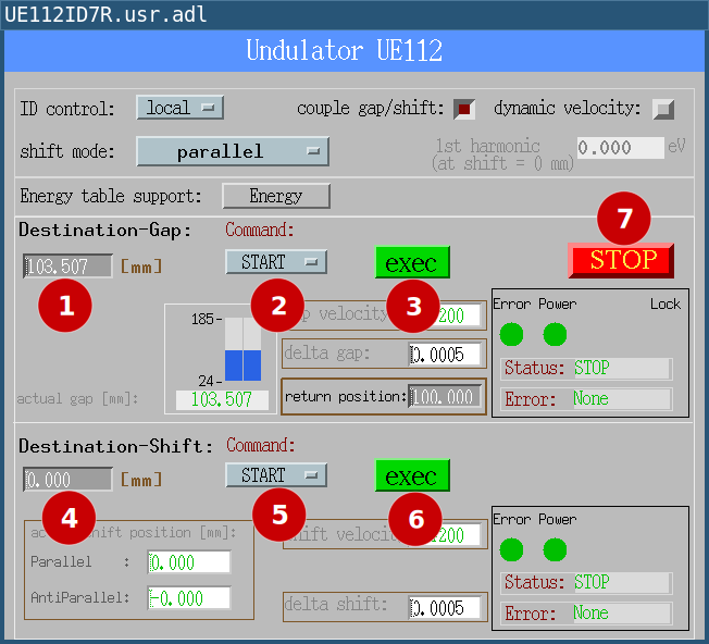
These are the controls, you can click on each item for further information:
The following picture shows a number at each secondary control element in the user panel:
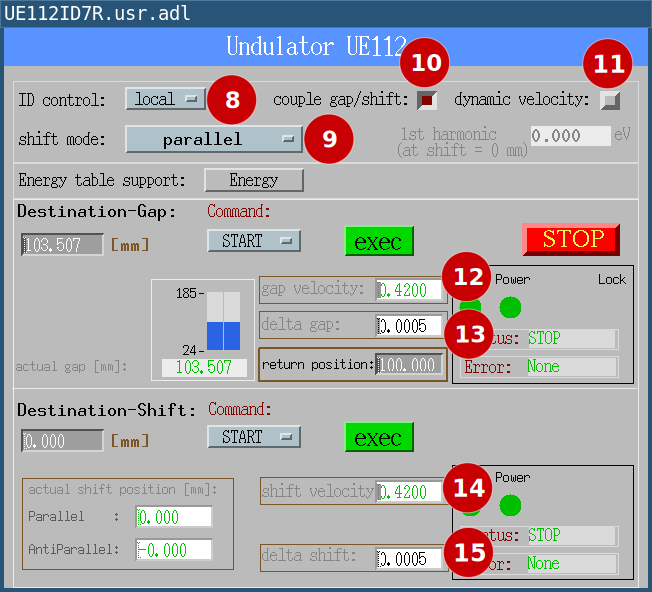
These are the controls shown here, you can click on each item for further information:
gap velocity
delta gap
shift velocity
delta shift
Energy Panel
This is the panel for energy table support.
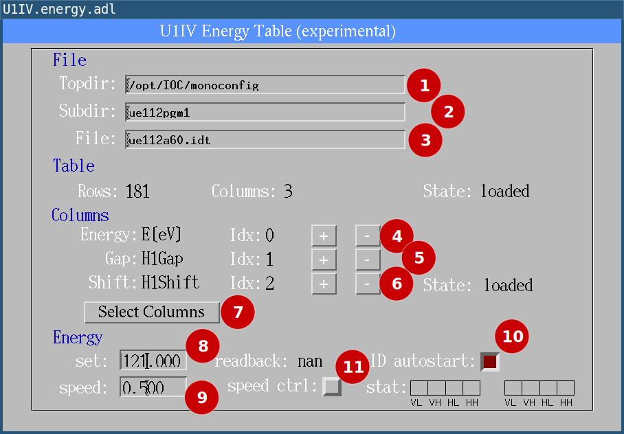
These are the controls here:
Advanced concepts
Dynamic speed
“Dynamic speed” is the ability to change the speed of gap or shift axles while the axles are moving.
The idea is to have one extra speed factor for the gap- and the shift drive that is a number between 0 and 1. This number is multiplied with the speed setting from the panel to give the actual speed. So the speed factor can only be used to reduce the actual velocity, not to increase it.
The implementation of the speed factor guarantees that a change of the speed factor is send to all axles at the same time. After the IOC has received a new speed setting, it should send the new value to the axles in 1 to 10ms. The time jitter between the axles is below 2 ms.
The speed factor for gap- and shift drive must be set for both with a single command (one EPICS waveform record) so all speed changes are applied to all gap- and shift axles at the same with (within 2ms).
Activating Dynamic Speed
When you intend to use Dynamic Speed you should activate gap/shift coupling to start a movement of the gap- and shift drive exactly at the same time, see couple gap/shift.
Then activate dynamic speed, see dynamic speed.
Setting Dynamic Speed via Channel Access
If dynamic speed is activated the speed can be changed by writing to:
[DEVICE]:DiagSpdSet
This is a waveform record with two elements, so you have to write two numbers to this PV. Here is an example:
caput -a UE112ID7R:DiagSpdSet 2 0.5 0.25
In this example, the gap drive now moves with 50% of it’s maximum velocity and the shift drive moves with 25% of it’s maximum velocity.
Setting Dynamic Speed via the CAN Bus
All the functions described above can be set by the CAN Bus, too, see dynamic speed via CAN Bus.
Energy Table Support
Warning
This feature is experimental, it is not yet available on all undulators. Errors may occur, some things may not work as expected. However, it is safe to use in the sense that no errors should occur that users cannot reset themselves. Just set dynamic speed off, maybe also couple gap/shift and you can use the undulator in the usual way.
Energy tables in general map a photon energy to gap- and shift position of an undulator.
The spectrum of the emitted light at an undulator has several sharp maxima, called harmonics, so we have actually a fourth variable, the number of the harmonic, usually an odd number.
In order to use the undulator at the beamline, the user selects the energy and the number of the harmonic. Both are entered at the monochromator control panel which calculates gap and shift from an energy table the user has selected and sends a command to the undulator control IOC to move to that gap and shift.
With energy table support, the undulator control program can now also load an energy table. The user can select the harmonic in the table by selecting matching columns interactively. He can then enter a photon energy at the undulator control panel and the undulator immediately starts moving to that energy.
It is also possible to move the undulator in a way that the photon energy during the movement changes with constant speed. e.g. 0.5eV/s.
The new feature has a new panel, “energy”.
How to load an energy table
The energy table must be located on host nfs.blc.bessy.de. The file path is
constructed from three fields, Topdir,
Subdir and File.
Topdir is pre-set with “/opt/IOC/monoconfig”, Subdir is optional and File is usually used for the filename without path.
For example, to load “/opt/IOC/monoconfig/ue112pgm1/h1a45a.idt” you set:
Topdir to “/opt/IOC/monoconfig”
Subdir to “ue112pgm1”
File to “h1a45a.idt”
The file is loaded immediately, when you change File. If the file cannot be loaded, an error message is displayed.
How to select table columns
Be default, the program selects column 1 for the energy, column 2 for the gap and column 3 for the shift values.
In the panel, you can click on “+” and “-” at “Energy”, “Gap” and “Shift” to select different columns. You then have to click on Select columns to make the changes active.
How to select an energy
Note
You should select couple gap/shift for this.
After you have loaded an energy table and selected the columns you can enter an energy at “Energy set”. Gap and shift for that energy are taken from the energy table and set as destinations.
If you select ID autostart, the undulator will start it’s movement immediately after you changed the energy. If couple gap/shift is selected, gap and shift drive start their movement at the same time.
Note
“Energy” “readback” is the current photon energy. This is only defined if the undulator was moved to a certain energy like described above and it is either not moving or you use a defined energy-speed (see below). In all other cases the current energy is not defined and the PV has the value “nan” (not a number).
How to move with constant energy speed
If you select couple gap/shift, and speed control in the Energy panel, you can move the undulator with constant energy speed, The speed is set at “Energy speed”.
In this case, the photon energy is well defined during movement and can be seen at “Energy” “readback”.
If you reach velocity limits for the drive during movement, the energy is no longer well defined. When this happens, you set red lights at “stat” in the panel. Usually, when this happens, you energy speed setting is too high. Try to make it a bit smaller.